





All postsEmergency versions and their labelingBasic technical information and concepts in lighting technologyDegree of resistance IKDegrees of protection IPBasic technical information on explosive atmospheres

Emergency versions and their labeling

The combination of electrical components in the light fixtures determines the lighting control system and how the fixtures operate when disconnected from the power supply.

EXTRA-EX1/21-J-L15-850-9800-NM3A-09-PD-3F

Basic Combinations of Electrical Components in VYRTYCH Light Fixtures: The combinations of electrical components in light fixtures determine the lighting control system and how the fixtures operate when disconnected from the power supply.

EXTRA-EX1/21-J-L15-850-9800-NM3A-09-PD-3F

Basic combinations of electrical components in VYRTYCH light fixtures:
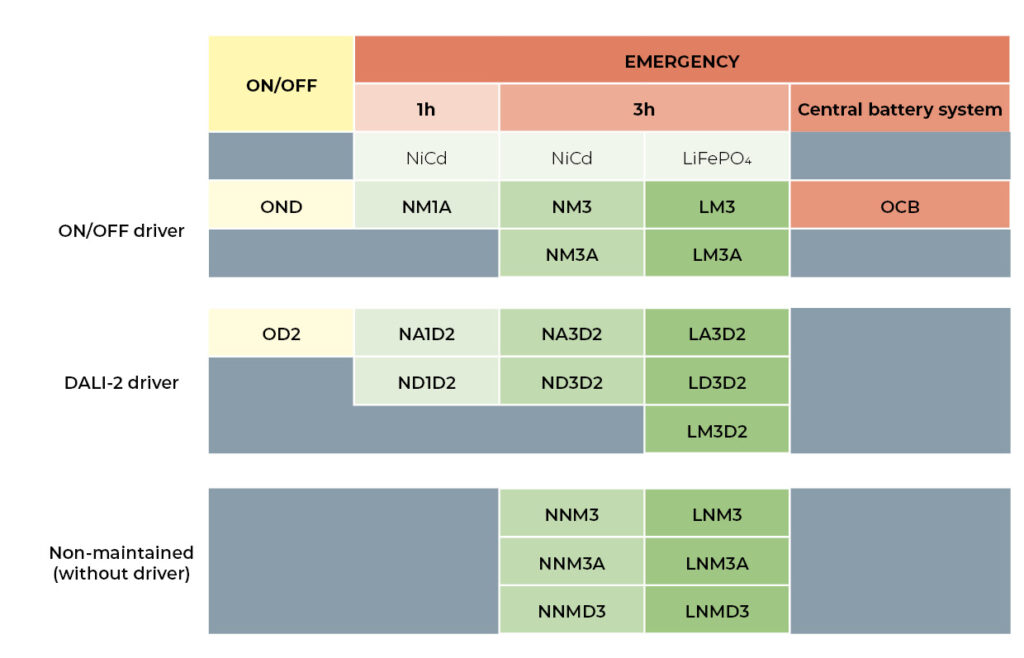
A light fixture with an ON/OFF ballast can be turned off using a standard light switch. It may or may not include an emergency power supply. If it includes an emergency unit, the light fixture will turn on for a minimum defined period—either 1 or 3 hours—using its own battery power in the event of a power outage. Lighting in emergency mode is limited to a lower luminous flux compared to when the light is not in emergency mode.

A luminaire with a ballast controlled via the DALI-2 protocol may or may not include a backup emergency module for illumination during a power outage. The luminaire can be controlled and dimmed in standard mode using the DALI-2 protocol, regardless of whether it is equipped with an emergency module.

M1/M3

Light fixtures that are designated by a combination of letters M1 or M3 They include a basic emergency module. The module is equipped with a test button (in some cases, designed for use with a magnet). The light fixture must then be tested by pressing the button to verify its operation in emergency mode. If the indicator LED begins to flash, it indicates a malfunction of the light fixture. You must go to the light fixture and manually check its status.

A1/A3/M3A

Light fixtures whose names include the designation A1 or A3 or M3A They are equipped with an emergency module featuring a self-test function. This function automatically tests the light fixture at regular intervals and, thanks to a two-color LED indicator, shows whether a test is in progress and, if necessary, whether the light fixture is malfunctioning. You must go to the light fixture and visually inspect it.

D1/D3/MD3

Light fixtures containing a DALI emergency module labeled D1 or D3 or MD3 They are connected to the DALI network via this module and then report their status using the DALI protocol in the relevant application. The lights are automatically tested for proper operation by the system. There is no need to physically check the lights to verify that their emergency mode is functioning properly.

0CB

Light fixtures designed for connection to a central battery system include a ballast that is tested for connection to battery systems and can also be powered by a DC power source. Central battery systems with so-called addressable monitoring must include an addressable module. Addressable modules are manufactured by various manufacturers, and Vyrtych can utilize a wide range of these modules from different manufacturers. We offer such luminaires upon request based on precise specifications.

Non-continuous-lighting fixtures do not contain a ballast that would power the light sources in the event of a power outage. These fixtures only illuminate when their power supply is interrupted. The luminaires may include emergency modules that function as standard emergency modules with a test button, as modules with a self-test function, or as modules that communicate via the DALI bus.
Basic technical information and concepts in lighting technology

Light and radiation
By light we mean the part of electromagnetic radiation that produces a light sensation in the human eye, i.e. it can be seen. It is radiation between 380 and 780 nm, i.e. only a tiny part of the known spectrum of electromagnetic radiation.

Luminous flux φ - unit lumen [lm]
Luminous flux indicates how much light the light source emits in total in all directions. It is the light output that is judged in terms of the sensitivity of the human eye.

Light source power Ŋ - unit lumen per Watt [lm/W]
The specific luminous flux indicates the ratio of luminous flux to the power input of the source, i.e. how efficiently the supplied electrical power is converted into light.

Luminance I - candela unit [cd]
A light source generally emits its light flux in different directions with different strengths. The intensity of light emitted in one particular direction is referred to as luminous intensity. Luminance is therefore a measure of the luminous flux emitted at a spatial angle.

Illuminance E - unit lux [lx]
Illuminance indicates the ratio of the incident luminous flux to the illuminated
area. Illumination intensity of 1 lx corresponds to a luminous flux of 1 lm incident
evenly over an area of 1 m2.

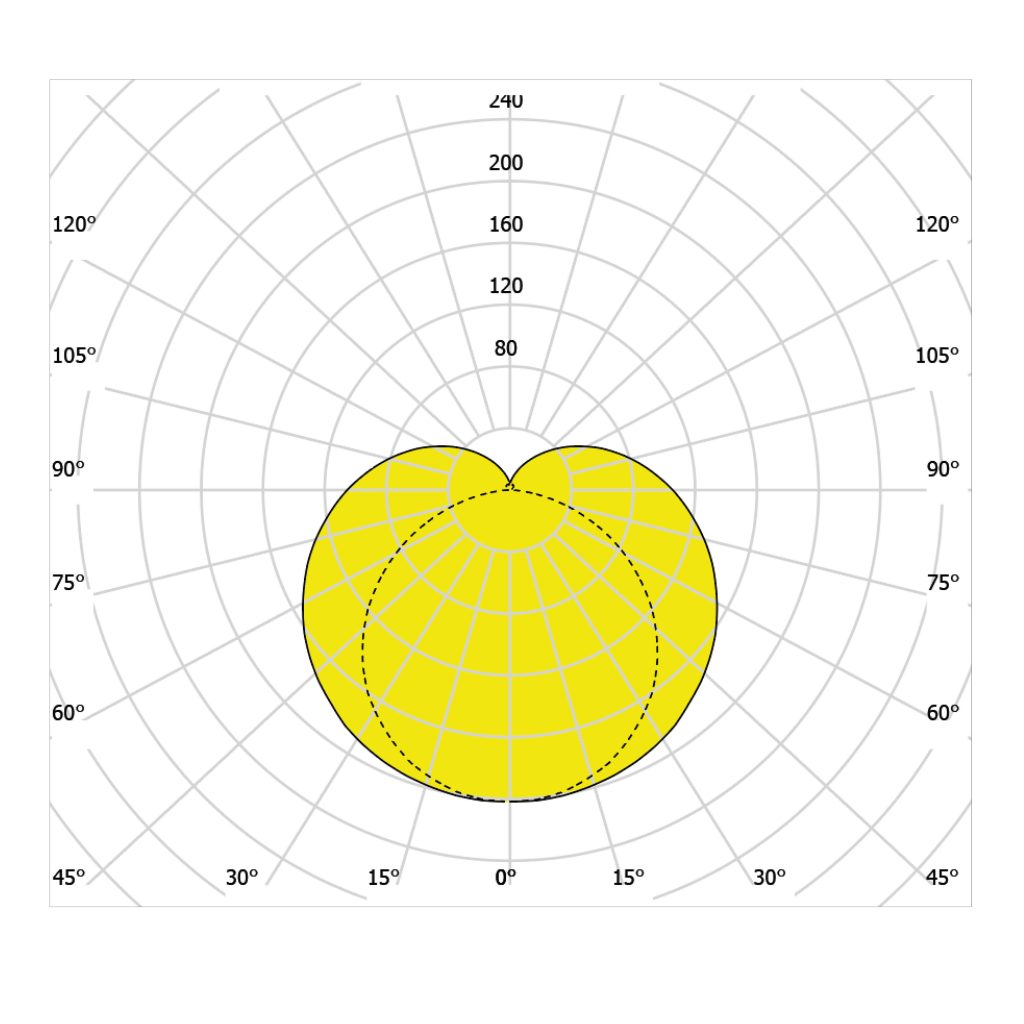
Luminance lines or luminance curves

These are curves that describe the luminance distribution of the luminaire in the individual planes of the C-γ system. The luminance lines are given in polar coordinates to give a more visual idea of the luminaire radiation. Their conversion into data usable for calculations is represented by ldt or ies files. The values shown in the graphs have the unit cd/klm.

Color Rendering Index Ra (CRI - color rendering index)
Color rendering fidelity CRI is a dimensionless unit that evaluates the fidelity of the color perception of an object illuminated by a particular light source against the fidelity of the color perception that would be produced by the sun. The CRI value can take values from 0 to 100.

Chromaticity temperature Tc - unit Kelvin [K] (CCT - correlated color temperature)
It characterises light by its temperature, which corresponds to the temperature of a blackbody emitting in the same colour spectrum. The lower the numerical value, the more red the colour of the light; the higher the value, the more blue the colour of the light.

Degree of resistance IK

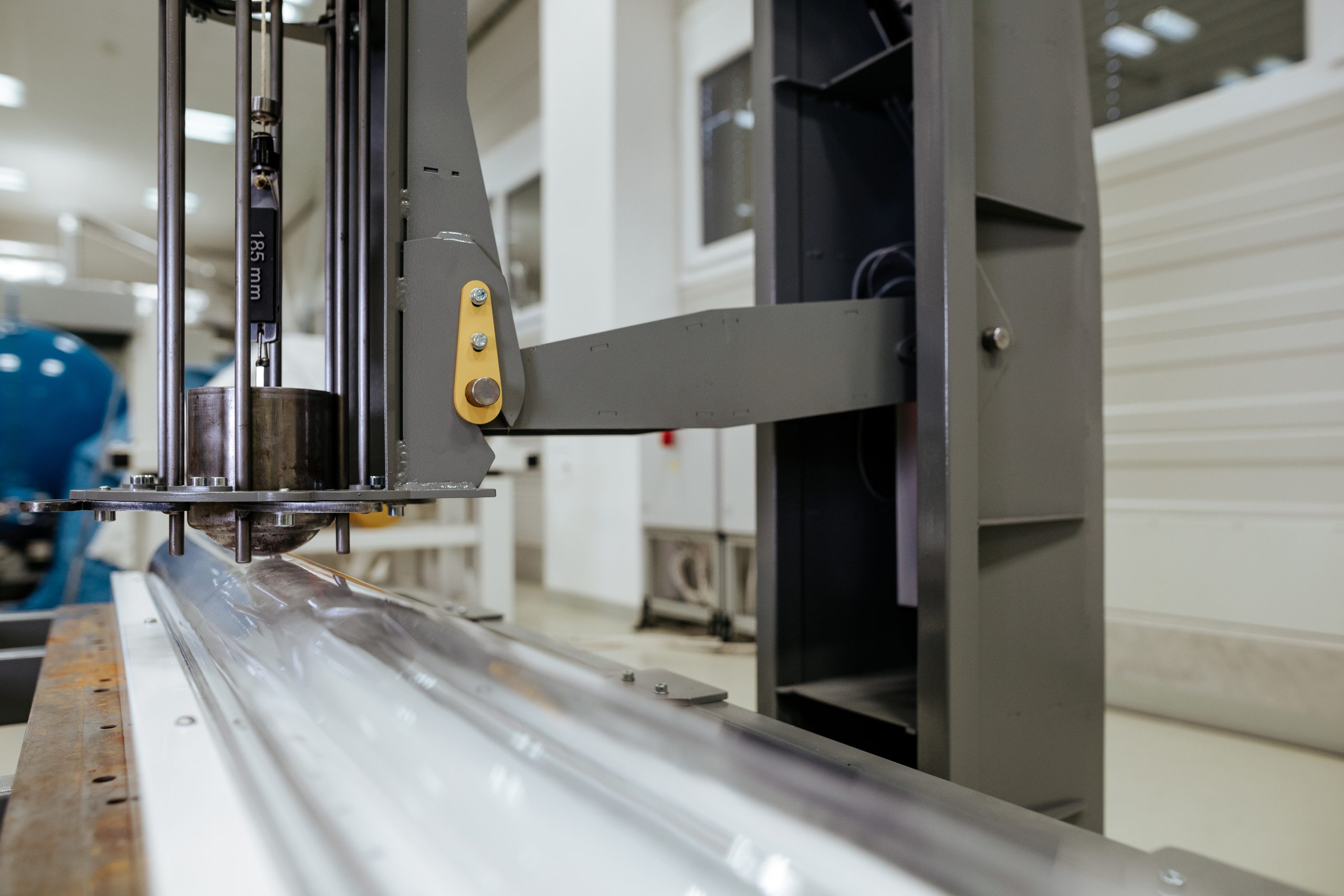
The degree of protection against external mechanical impacts, the classification of mechanical resistance IK is determined by the European standard ČSN EN 62262.

The IK mechanical resistance classification determines the degree of protection that provides the device with protection against external mechanical impacts. The mechanical resistance designation consists of the letters IK and indicates its level on an eleven-step scale ('00' to '10').

The higher the numerical value of the IK parameter, the higher the mechanical resistance.

IK00Without impact protection
IK01Impact resistance equivalent to a 200 g weight falling from 7.5 cm
IK02Impact resistance equivalent to a 200 g weight falling from 10 cm
IK03Impact resistance equivalent to a 200 g weight falling from 17.5 cm
IK04Impact resistance equivalent to a 200 g weight falling from 25 cm
IK05Impact resistance equivalent to a 200 g weight falling from 35 cm
IK06Impact resistance equivalent to a 500 g weight falling from 20 cm
IK07Impact resistance equivalent to a 500 g weight falling from 40 cm
IK08Impact resistance equivalent to a 1.7 kg weight falling from 29.5 cm
IK09Impact resistance equivalent to a 5 kg weight falling from 20 cm
IK10Impact resistance equivalent to a 5 kg weight falling from 40 cm
IK11Impact resistance equivalent to a 10 kg weight falling from 50 cm

Degrees of protection IP

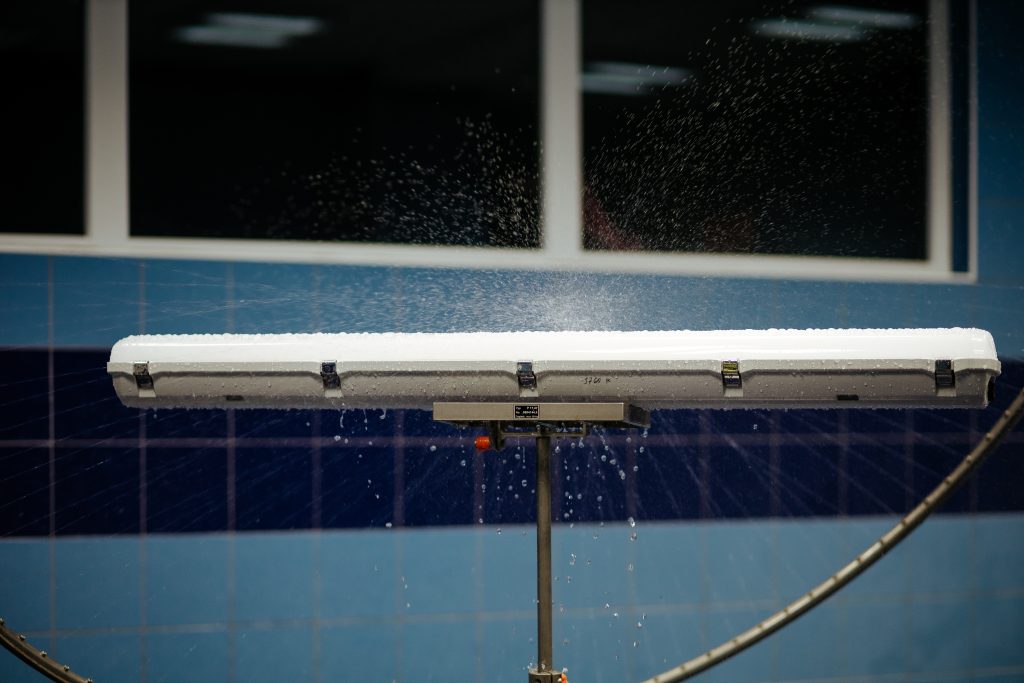
The enclosure of electrical equipment expresses the degree of protection against contact with dangerous parts and against the ingress of foreign solids, dust and water. The degree of protection is indicated by the letters IP (international protection) and is standardised according to EN 60529.
After the letters IP there is a characteristic double protection number, or an additional and supplementary letter that describes the test method.

GRADEPROTECTION AGAINST SOLID BODIESGRADEWATER INGRESS
IP 0xWithout protectionIP x0Without protection
IP 1xProtection against bodies larger than 50 mmIP x1Protection against vertically falling water
IP 2xProtection against bodies larger than 12.5 mmIP x2Drip protection at 15° inclination
IP 3xProtection against bodies larger than 2.5 mmIP x360° splash protection
IP 4xProtection against bodies larger than 1 mmIP x4Protection against splashing water from all directions
IP 5xPartial protection against dust ingressIP x5Protection against gushing water from all directions
IP 6xComplete protection against dust ingressIP x6Protection against intense water current
IP x7Protection when immersed in water up to 1 m deep for 30 min
IP x8Protection when permanently immersed in water under conditions specified by the manufacturer
IP x9Protection against high pressure hot water

If the luminaire is marked IP66/IP67/IP69, this means that it meets three separate protection tests.

Basic technical information on explosive atmospheres

ATEX Directive
Electrical equipment and apparatus intended for use in potentially explosive atmospheres that are subject to the requirements of the ATEX Directive. This Directive sets out the technical requirements for the assessment of the conformity of equipment and protective systems intended for use in potentially explosive atmospheres when they are placed on the market.

Installations are divided into appropriate groups and categories according to this Directive.

Equipment group I - Installations for underground mines with the presence of mine gas (methane) and/or combustible dust.

Equipment Group II - Installations for explosion hazardous areas outside underground mines with the presence of mine gas (methane) and/or combustible dust.

(a) Category 1 GD equipment
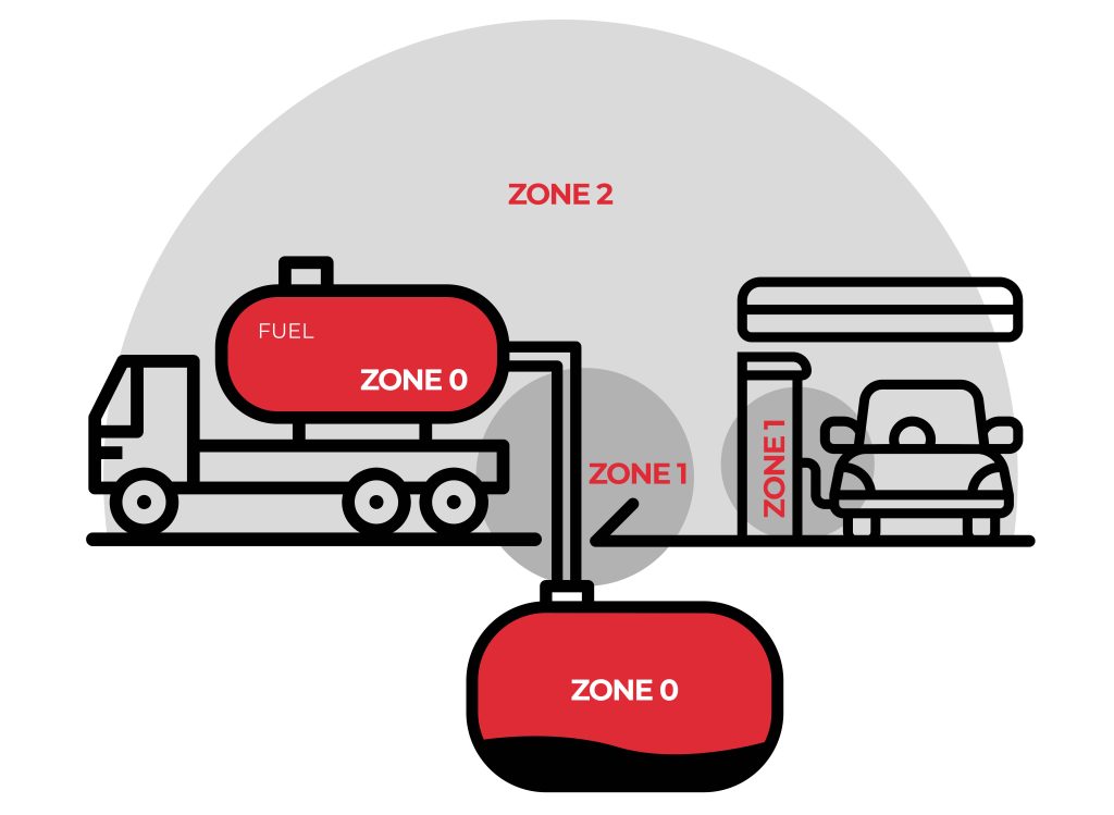
It includes installations designed to operate in accordance with the operating parameters specified by the manufacturer and to provide a very high level of protection. Installations in this category are intended for use in areas where explosive atmospheres created by gases, vapours, mists or mixtures of dust and air occur on a continuous, prolonged or frequent basis. Installations in this category must provide the required level of protection even in the event of exceptional equipment-related events.
ZONE 0/20 (Ga, Da)

(b) Equipment category 2 GD
It includes installations designed to operate in accordance with the operating parameters specified by the manufacturer and to provide a high level of protection. Installations in this category are intended for use in areas where explosive atmospheres may occasionally be created due to the presence of gases, vapours, mists or mixtures of dust and air.
The protection measures applicable to installations in this category ensure the required level of protection even in the event of frequent faults or equipment failures that must be taken into account on a regular basis.
ZONE 1/21 (Gb, Db)

(c) Equipment category 3 GD
It includes installations designed to operate in accordance with the operating parameters specified by the manufacturer and to provide a basic level of protection. Installations in this category are intended for use in areas where explosive atmospheres created by gases, vapours, mists or dusts are unlikely to occur and, if they do occur, are likely to occur only rarely and for short periods of time. Installations in this category provide the required level of safety during normal operation.
ZONE 2/22 (Gc, Dc)

×
  BECOME A PARTNER